


A highly efficient and compact electric power source is required on the battlefield in order to operate telecommunication devices, night-vision goggles, sensors, portable computers, and unmanned aerial vehicles. While batteries can provide the power needed for short-term missions, they come with several limitations. It is impossible for warfighters to carry a sufficient number of batteries for a mission longer than a few days.
As a result, much research and development attention has turned to fuel cells—an electrochemical device that converts a fuel’s chemical energy into electric power—for long-duration applications [1–3]. The most efficient fuel cells use hydrogen as their fuel source, as it has high power, high energy, and zero CO2 emissions [4].
An innovative, in situ hydrogen generation fuel cell has been developed at the U.S. Army Combat Capabilities Development Command’s Army Research Laboratory (ARL) for future warfighter power systems. The fuel cell is composed of two functional parts: one for hydrogen generation, by methanol electrolysis; and the other for electric power generation, through an internal hydrogen/air power plant. No external tank is required to store compressed hydrogen gas, and all hydrogen generated is used instantly by the hydrogen/air fuel cell. The hydrogen gas generated in the first part is directly transported to the second part through a 2mm thick junction electrode for electricity generation.
For use in the in situ fuel cell, our team at ARL developed high-potential cathode catalysts for hydrogen evolution and oxygen reduction, and anode catalysts for alcohol electrooxidation. Experimental results to date have demonstrated that 100g of methanol can be converted to ~16.8g of hydrogen gas (excluding the mass of water). A prototype has been tested by running methyl alcohol. A fuel energy density of approximately 1,300 Wh/kg of fuel was achieved—a level 56% higher than standard methanol-reforming fuel cells (~830 Wh/kg) [5]. This technology will enable the warfighter to power a variety of electric devices with a compact, lightweight, high-power, and high-energy power source capable of powering longer missions than those supported by batteries alone.
Hydrogen-Generation Fuel Cell Technologies
Several onboard hydrogen-generation technologies have been proposed by using hydrogen rich solid or liquid materials to produce hydrogen gas for fuel cells. The U.S. Army evaluated three of these technologies for onboard hydrogen generation for fuel cells.
The first is thermal decomposition of alane (AlH3), which has a theoretical hydrogen content of 10% (wt%) and an experimental hydrogen yield of 7.7–9.2% (wt%) [6–8]. Although the initial release of hydrogen gas occurs at <100°C from alane, the full hydrogen yield cannot be obtained despite temperatures as high as >250°C. Furthermore, the high temperature decomposition of alane causes pressure buildup and safety concerns [8].
The second candidate for onboard hydrogen generation is hydrolysis of aluminum (Al) metal nanoparticles by the reaction of Al with water, which requires large amounts of water for a water/Al ratio >3/1 [9–11]. The Al method’s theoretical hydrogen yield is only 3.7% (wt%), including water. Adding a large quantity of water limits automobile and portable electronics applications.
The third candidate is onboard thermal-reforming methanol to generate hydrogen gas for a fuel cell [12–13], which needs about 30% water for methanol steam reforming at 200–300°C. In order to maintain a high reforming temperature, additional methanol must be burned in the thermal-reforming methanol fuel cell, which further lowers the fuel energy density and results in a density ~830 Wh/kg. In addition, thermally reforming methanol causes a carbon monoxide (CO) release as high as 1,000 ppm at startup, which creates an inhalation safety concern. (These results were obtained from ARL’s evaluation of several reforming methanol fuel cell systems manufactured by UltraCell, LLC.)
In a methanol-reforming fuel cell, the process of reforming must be carried out at 250–300oC to generate and store hydrogen gas. The temperature of hydrogen from the reformer is too high for a polymer electrolyte membrane fuel cell (20–100°C), and also too high for a fuel cell using polybenzimidazole as an electrolyte membrane (160–180°C). All methanol-reforming fuel cell systems require a cooling system. These high operating temperatures create issues related to cost, complex system design, slow startup and shutdown cycle speeds, and a shortened lifespan.
After reviewing these onboard-hydrogen generation technologies, we designed, constructed, and evaluated a prototype of an innovative in situ hydrogen generation fuel cell capable of providing electric power continuously. The in situ hydrogen fuel cell works at low temperatures (20–90°C) to electrochemically process methanol for hydrogen generation and electric power generation, simultaneously. Unlike other hydrogen generation architectures, the in situ prototype does not need to carry a compressed hydrogen gas tank, as its hydrogen is self-produced via hydrogen-rich alcohols.
Method of Electrochemically Converting Methanol to Hydrogen
Methanol can be electrochemically converted into hydrogen within an electrochemical cell. At the anode:
CH3OH + H2O = CO2 + 6H+ + 6e–, and E0 = 0.02V. (1)
At the cathode:
6H+ + 6e– →3H2, and E0 = 0.0V. (2)
The overall electrochemical reaction is:
CH3OH + H2O = CO2 + 3H2, and E0cell = 0.02V. (3)
Theoretically, we only need to apply a 20-mV electric voltage to convert methanol to hydrogen gas. That is, we only need to apply a small amount of energy to convert methanol into hydrogen gas by a method of electrolysis, and then use the hydrogen to generate more electrical energy. This is a very promising method for producing hydrogen on demand. Furthermore, methanol has a high hydrogen content of 12% by mass, including water, and 18.75%, excluding water. Because the in situ fuel cell generates water, if the generated water is recycled, the hydrogen yield may approach 18% by mass.
Experimental results demonstrated that 90% hydrogen yield can be obtained electrochemically for hydrogen generation [14]. Therefore, 100g of methanol can be converted up to 16.8g hydrogen gas (excluding the mass of water). Compared to alane, Alnanoparticles (or Al-alloy), and thermal reforming technologies for hydrogen generation, the methanol electrolysis technology has the highest hydrogen yield. In addition to methanol, several other alcohols can be used to generate hydrogen (e.g., iso-propanol alcohol [rubbing alcohol]). Figure 1 shows hydrogen generation at the cathode electrode of an electrochemical apparatus [14] by electrolysis of 4M 2-propanol alcohol.
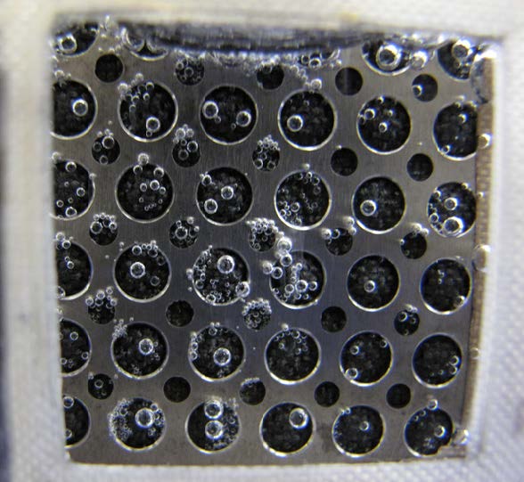
Figure 1. Hydrogen generation at thecathode electrode
Design and Assembly of an In Situ Hydrogen Generation Fuel Cell Prototype
In order to realize in situ generation of hydrogen gas, we designed, assembled, and experimentally tested a fuel cell prototype [15]. Figure 2 presents a schematic view of a methanol-fueled in situ hydrogen generation fuel cell. The prototype is composed of two functional parts—one for hydrogen generation by methanol electrolysis and the other for electric power generation through a hydrogen/air fuel cell. The two parts share a junction electrode, which is a cathode for the hydrogen generation electrolyzer, and an anode for hydrogen/air fuel cell. This junction electrode is designed with micropores for gas and water transport. This design minimized the distance of hydrogen gas transfer between the hydrogen generation electrolyzer and the hydrogen/air fuel cell. The hydrogen transfer distance is less than 2mm across a junction electrode. As long as the hydrogen is generated, it is used instantly for electric power generation in the part of hydrogen/air fuel cell. By eliminating the need for an external gas tank, the in situ fuel cell reduces the weight and size of a hydrogen fuel cell system.
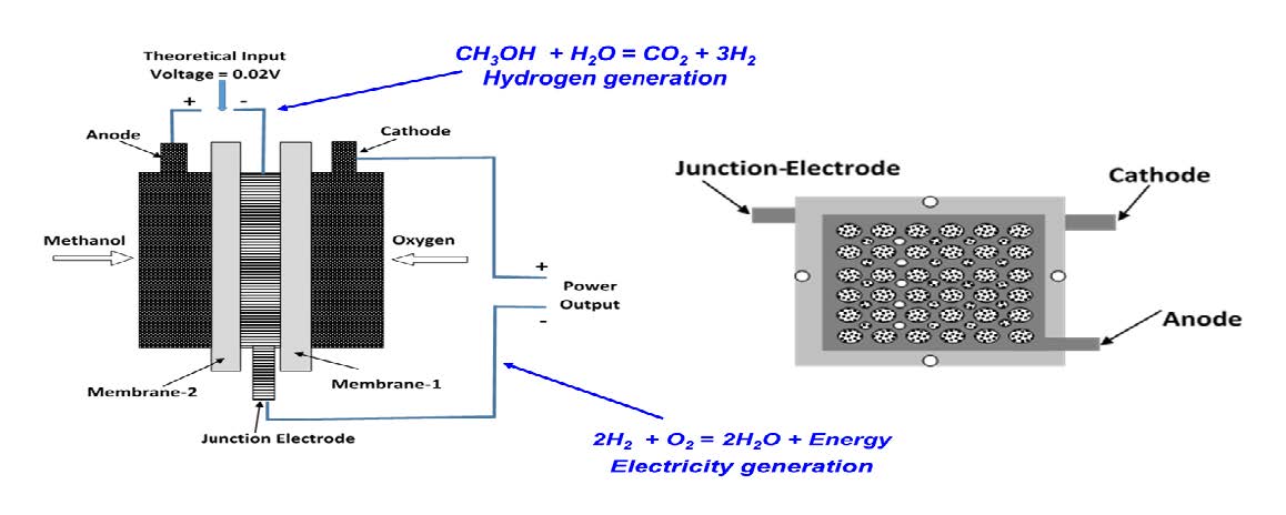
Figure 2. Schematic view of an in situ hydrogen generation fuel cell using methanol to generate hydrogen. (Left) A combination of an electrolyzer and a fuel cell joined by a junction electrode and (Right) experimental components containing three electrodes and two electrolyte membranes.
Evaluation and Results
We built experimental prototypes and examined the feasibility of an in situ hydrogen generation fuel cell (see Figure 2). A single unit of the prototype (see left photo in Figure 3) consists of two membrane electrolyte assemblies (MEAs)—one as an electrolyzer for hydrogen generation and the other as a hydrogen/air fuel cell for electric power generation. A junction electrode was positioned between membrane-1 and membrane-2 (see left diagram in Figure 2). The single unit prototype was used for the experimental proof of the proposed concept’s feasibility. The bi-unit
of the prototype (see right photo in Figure 3) is a combination of two single units, which was used for demonstrations such as running a small electric fan.
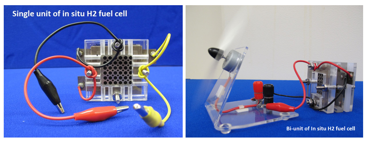
Figure 3. Single unit (Left) and bi-unit (Right) of in situ hydrogen fuel cells using methanol to generate hydrogen
Figure 4 shows experimental results obtained from a single unit of prototype [14]. Here, 6mL 1.0M methanol is filled into the fuel chamber and the temperature is held at 30°C. The input voltage (CH voltage), or the electrolyzer’s voltage, is constant at 0.30V, and the output voltage (DCH voltage), or the fuel cell’s voltage, responds at 0.80V. The overall net voltage output is 0.50V. In this example, the input current (CH current) is provided by an external power for the electrolyzer, and the output current (DCH current) is generated by a hydrogen/air fuel cell. The
experimental result shows that the input current is approximately equal to the output current or ~100% coulomb efficiency from the fuel processing electrolyzer to the fuel cell is obtained. The methanol is first converted into hydrogen in the fuel-processing electrolyzer. Meanwhile, the hydrogen is simultaneously used in the hydrogen/air fuel cell for electric power generation.
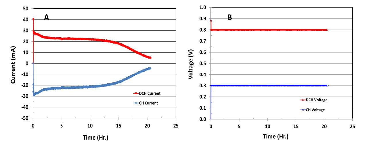
Figure 4. Performance of a prototype of in situ hydrogen generation fuel cell operated with6-mL, 1.0M methanol at 30°C
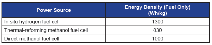
Figure 5 shows fuel energy density obtained with a single unit of in situ hydrogen generation fuel cell. This single unit prototype is operated with 6mL 1.0M methanol at 30°C. Here, CH voltage is held at 0.4V, and DCH voltage responds at 0.75V. The energy density obtained from this prototype is 1,300 Wh/kg (fuel only). Table 1 lists energy density obtained from three types of fuel cell systems evaluated at ARL. The in situ hydrogen generation fuel cell gives the highest fuel energy density, which is 56% higher than the thermal-reforming methanol fuel cell.
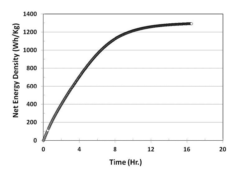
Figure 5. Net energy density obtained froma prototype of in situ hydrogen generationfuel cell operated with 6mL, 1.0M methanolat 30°C
Table 1. Comparison of energy density from three types of fuel cell systems at ARL
The Role of Electrode Catalysts
Practically, methanol is not electrooxidized at the anode, nor is hydrogen generated at the cathode by applying only a theoretical potential of 20mV. This is due to overpotentials caused by slow electrode kinetics and the fuel cell’s internal resistance. Therefore, we had to develop efficient electrode catalysts for sufficiently lowering the overpotentials of methanol electrolysis. At ARL, we developed high-potential cathode catalysts for hydrogen evolution and oxygen reduction, and anode catalysts for alcohol electrooxidation [15–17]. Figure 6 shows transmission electron microscopic (TEM) images of a PtCo cathode catalyst [15, 18] and PdNiP anode catalyst [16].
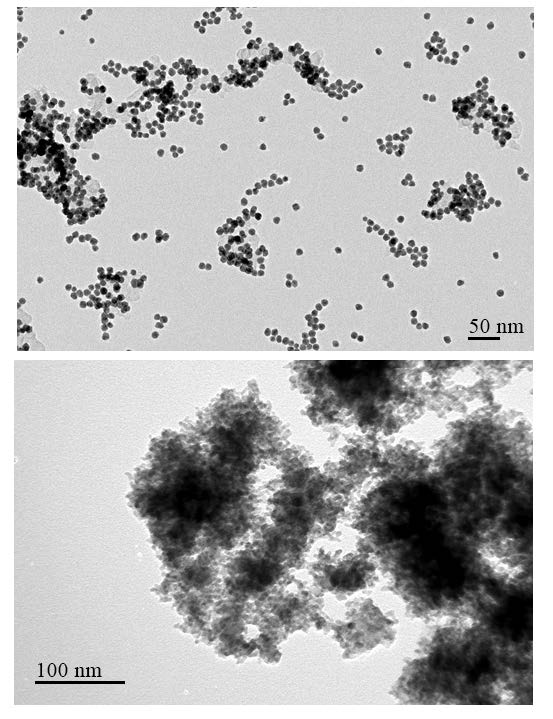
Figure 6. TEM images of cathode catalyst ofPtCo (Top) for hydrogen evolution and oxygenreduction and anode catalyst of PdNiP(Bottom) for alcohol electro-oxidation
Conclusion
The hydrogen-powered fuel cell is a promising power source for the Department of Defense, capable of providing continuous electric power for long-term missions. Our experimental results demonstrate that 100g methanol can be converted into ~16.8g hydrogen gas, excluding the mass of water. These results could help make significant strides in meeting the challenges of supplying the warfighter with ample expeditionary power, by generating on-demand energy unencumbered by hydrogen gas storage tanks.
Acknowledgments
The authors would like to thank Drs. Deryn Chu and Cynthia Lundgren for their discussions and the U.S. Department of the Army and U.S. Army Materiel Command for supporting this work.
References
1. Srinivasan, S. (1989). Fuel cells for extraterrestrial and terrestrial applications. Journal of the Electrochemical Society, 136(2). doi:10.1149/1.2096647
2. Bacon, F. (1969). Fuel cells, past, present and future. Electrochimica Acta, 14(7), 569–585. doi:10.1016/0013-4686(69)87042-8
3. Perry, M. L., & Fuller, T. F. (2002). A historical perspective of fuel cell technology in the 20th century. Journal of the Electrochemical Society, 149(7). doi:10.1149/1.1488651
4. Colella, W., Jacobson, M., & Golden, D. (2005). Switching to a U.S. hydrogen fuel cell vehicle fleet: The resultant change in emissions, energy use, and greenhouse gases. Journal of Power Sources, 150, 150–181. doi:10.1016/j.jpowsour.2005.05.092
5. ARL have evaluated several methanol-reforming fuel cell systems from UltraCell, LLC. At optimized operating condition, these fuel cell systems gave power output of 20–25 watts with fuel energy density ~830 wh/kg.
6. Ahluwalia, R., Hua, T., & Peng, J. (2009). Automotive storage of hydrogen in alane. International Journal of Hydrogen Energy, 34(18), 7731–7740. doi:10.1016/j.ijhydene.2009.07.013
7. Thampan, T., Atwater, T., Cook, C., Novoa, J., & Sutorik, A. (2016). Hydrogen generation from aluminum hydride for wearable polymer electrolyte membrane fuel cells. International Journal of Hydrogen Energy, 41(22), 9402–9409. doi:10.1016/j.ijhydene.2016.04.095
8. Grew, K. N., Brownlee, Z. B., Shukla, K. C., & Chu, D. (2012). Assessment of alane as a hydrogen storage media for portable fuel cell power sources. Journal of Power Sources, 217, 417–430. doi:10.1016/j.jpowsour.2012.06.007
9. Huang, X., Gao, T., Pan, X., Wei, D., Lv, C., Qin, L., & Huang, Y. (2013). A review: Feasibility of hydrogen generation from the reaction between aluminum and water for fuel cell applications. Journal of Power Sources, 229, 133–140. doi:10.1016/j.jpowsour.2012.12.016
10. Rosenband, V., & Gany, A. (2010). Application of activated aluminum powder for generation of hydrogen from water. International Journal of Hydrogen Energy, 35(20), 10898–10904. doi:10.1016/j.ijhydene.2010.07.019
11. Prabu, S., Hsu, S., Lin, J., & Wang, H. (2018). Rapid hydrogen generation from the reaction of aluminum powders and water using synthesized aluminum hydroxide catalysts. Topics in Catalysis, 61(15-17), 1633–1640. doi:10.1007/s11244-018-0970-x
12. Iulianelli, A., Ribeirinha, P., Mendes, A., & Basile, A. (2014). Methanol steam reforming for hydrogen generation via conventional and membrane reactors: A review. Renewable and Sustainable Energy Reviews, 29, 355–368. doi:10.1016/j.rser.2013.08.032
13. Li, M., Duraiswamy, K., & Knobbe, M. (2012). Adsorption enhanced steam reforming of methanol for hydrogen generation in conjunction with fuel cell: Process design and reactor dynamics. Chemical Engineering Science, 67(1), 26–33. doi:10.1016/j.ces.2011.07.024
14. Jiang, R. Z., Tran, D. T., & Chu, D. D. (2015, September 8). Power-free apparatus for hydrogen generation from alcohol. U.S. Patent No. 9,127,370. Washington, DC: U.S. Patent and Trademark Office.
15. Rong, C., Jiang, R., Sarney, W., & Chu, D. (2010). Ultrasound-assisted micro-emulsion for synthesis of Pt and PtCo nano-particles. Electrochimica Acta, 55(22), 6872–6878. doi:10.1016/j.electacta.2010.05.078
16. Jiang, R., Rong, C., & Chu, D. (2011). Surface coverage of Pt atoms on PtCo nanoparticles and catalytic kinetics for oxygen reduction. Electrochimica Acta, 56(5), 2532–2540. doi:10.1016/j.electacta.2010.11.060
17. Jiang, R., Tran, D. T., Mcclure, J. P., & Chu, D. (2014). A class of (Pd–Ni–P) electrocatalysts for the ethanol oxidation reaction in alkaline media. ACS Catalysis, 4(8), 2577–2586. doi:10.1021/cs500462z
18. Jiang, R. Z., Tran, D. T., & Chu, D. D. (2017, January 3). Methods and apparatus of an anode/cathode (A/C) junction fuel cell with solid electrolyte. U.S. Patent No. 9,537,167. Washington, DC: U.S. Patent and Trademark Office.