


Separators and Electrodes in Fuel Cells and Batteries
The modern military relies heavily on portable electricity. The efficient generation, storage and distribution of electrical energy in a war zone are essential to sustaining military operations. New, highly mobile energy conversion and storage devices, like proton-exchange membrane fuel cells and next-generation lithium-ion batteries, will provide military forces with an energy- on-demand option for communications, logistical operations and weaponry. In this regard, continued research and development efforts are needed so the performance of such devices matches military needs.
Batteries store energy, whereas fuel cells convert a fuel (e.g., hydrogen) and oxidant (air) into electrical energy. While different in terms of their mode of operation, battery and fuel cells’ main hardware components are quite similar. Both contain high surface area anodes and cathodes, with an inter- electrode membrane or electrolyte-filled separator, which prevents electrode contact and provides ion transport pathways.
The electrodes contain dispersed active material, such as carbon-supported platinum catalyst in fuel cells or lithium storage particles (graphite and LiCoO2) in Li-ion batteries. In polymer electrolyte membrane fuel cells, a hydrated perflurorsulfonic acid polymer film (e.g., DuPont’s Nafion®) separates the electrodes and allows for facile proton transport during current flow. The separator in Li-ion batteries is usually a porous film prepared from polyolefins (polyethylene/ polypropylene), which is soaked in a liquid electrolyte during cell assembly.
At present, the high surface area porous electrodes in both batteries and fuel cells are fabricated by solvent evaporation from cast slurries containing active material and polymer binder. Dense fuel cell membranes are prepared from ionomer solutions by solvent casting or melt extrusion of the ionomer precursor, while porous battery separators are typically fabricated via a dry process involving extrusion of molten polymer (e.g., polyolefin) into a fabric which is then annealed and stretched under controlled thermal conditions to create the desired microporosity. While these fabrication techniques are commercially viable, they do not fully exploit the extraordinary performance characteristics of many newly developed nanomaterials.
Electrospinning is one option for the hierarchal organization of polymers and nanoparticles into membrane and electrode components for high-performance energy storage and conversion devices. Electrospinning processes are cost competitive and simple to realize on a commercial scale, with process equipment readily available for large-scale manufacturing. This paper provides a brief overview on the use of nanofiber electrospinning for fabricating fuel cell and battery components.
What is Electrospinning?
Electrospinning is a scalable technique for the fabrication of sub-micrometer diameter fibers composed of one or more polymers or mixtures of nanoparticles and a polymer binder. A standard electrospinning apparatus (See Figure 1) consists of a high voltage power supply, a fiber collector surface and one or more spinnerets. A polymer or particle/polymer solution or a polymer melt is
supplied to the spinneret(s) at a controlled flowrate. With a sufficiently high electric field between the spinneret tip and grounded collector (on the order of 0.5-3 kV/cm), a Taylor cone forms, from which of a small-diameter fiber jet emerges. As the jet travels towards the collector, it dries in flight and elongates by a whipping process. The elongation and thinning of the jet leads to the formation of a fiber mat, where the average fiber diameter is typically in the 100-600 nm range.
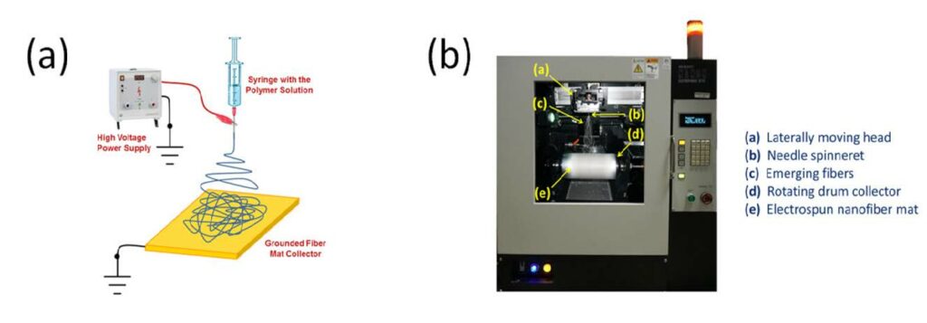
Figure 1: (a) Schematic diagram of the electrospinning process and (b) An example of a commercial lab-scale electrospinner from MECC, Japan. (Released)
Fiber electrospinning was invented in the early 1900s, but little interest was seen until the work of Reneker and co-workers in the 1990s. [1] In 2008, Pintauro and co-workers [2,3] used electrospinning to prepare nanocomposite fuel cell membranes as an alternative to traditional membrane fabrication methods and materials (e.g., cast polymer blends and copolymers).
In the resultant nanofiber composite membrane morphology, the proton conduction structure and function of the ionomeric material was decoupled from the mechanical support and swelling control functions of the uncharged polymer.
Recently, Pintauro’s group introduced nanoparticle/polymer hybrid fiber electrospinning for the fabrication of fuel cell and battery electrodes. Here, a concentrated suspension of electrochemically active nanoparticles (e.g., Pt/C, LiCoO2 or Si) and polymer binder in an organic solvent is electrospun to create a highly porous and robust fiber mat electrode. Such fiber mat
electrodes exhibited superior performance in hydrogen/air fuel cells and Li-ion batteries compared to conventional electrodes prepared by slurry/tape casting or sprayed droplet deposition. In the remainder of this paper, recent work from the present authors on electrospun fuel cell membranes, Ptbased fuel cell electrodes, and Li-ion battery electrodes is reviewed.
Electrospun Nanofiber Composite Membranes for Fuel Cells
Over the past 15 years, there has been unprecedented research and development activity worldwide in the field of fuel cells involving both academia and commercial enterprises. [4] The search for low-cost, high performance fuel cell membranes has been a significant part of this overall effort. Low/ moderate temperature hydrogen/air proton exchange membrane, or PEM, fuel cells are
highly efficient, ecologically-friendly energy conversion devices.
The key membrane properties for PEM fuel cells are: (i) a high proton conductivity, especially at low relative humidity air conditions; (ii) mechanical robustness, including resistance to wet/dry cyclic stresses; (iii) good oxidative and thermal stability; (iv) low permeability to the fuel and oxidant; and (v) low cost. A perfluorosulfonic acid polymer, or PFSA, membrane, such as Nafion® by
DuPont, fulfills some of these specifications, but their dramatic conductivity loss at low relative humidity and high price are serious barriers that need to be addressed.
Pintauro and co-workers introduced electrospinning as a novel platform for the fabrication of nanocomposite fuel cell membranes. [2,3,5,6] Such membranes were found to be viable alternatives to membranes based on polymer blends and block copolymers. Initially, the nanocomposite membranes were fabricated by electrospinning an ionomer fiber mat followed by mat impregnation by
an uncharged, inert polymer.
The resulting membrane morphology is shown in Figure 2. Alternatively, an uncharged polymer was first electrospun followed by ionomer impregnation into the nanofiber mat. One or more post-electrospinning processing steps were usually required to convert an electrospun mat into a dense defect-free fuel cell membrane (e.g., mat compression, ionomer annealing and rinsing in acid and water). These steps were dependent on the particular choice of charged and uncharged polymer. One can easily change the type of ionomer and uncharged polymer and the relative amounts
of each, to change membrane properties (e.g., conductivity, swelling or mechanical strength).
![Figure 2. Example of an electrospun composite membrane morphology. The uncharged polymer matrix (a) restricts swelling and imparts mechanical strength to the membrane, while the water-swollen fiber network (b) composed of an ionomer with sulfonic acid fixed charge groups (c) provides pathways for proton transport. [2] (Reprinted with permission. Copyright 2008 American Chemical Society/Released)](https://hdiac.org/wp-content/uploads/2021/04/2017nano-electrospun-energy-conversion-storage_fig23.jpg)
Figure 2. Example of an electrospun composite membrane morphology. The uncharged polymer matrix (a) restricts swelling and imparts mechanical strength to the membrane, while the water-swollen fiber network (b) composed of an ionomer with sulfonic acid fixed charge groups (c) provides pathways for proton transport. [2] (Reprinted with permission. Copyright 2008 American Chemical Society/Released)
Dual-fiber electrospinning was later introduced by Ballengee and Pintauro as an alternative to a separate pore-filling impregnation step for the fabrication of composite fuel cell membranes. [3] Here, both polymer components (ionomer and uncharged polymer) are simultaneously electrospun as separate fibers onto a common collector surface to create a mixed fiber mat. Subsequent
processing induces flow of one of the polymer components into the interfiber void space between fibers of the second polymer (after processing the nanofiber morphology of the second polymer is retained).
For example, a PFSA polymer (e.g., Nafion) was simultaneously electrospun with poly(phenyl sulfone) to create a dual fiber mat, which was then processed into a dense membrane with either one of the following structures: (i) an interconnected network of Nafion nanofibers encapsulated by PPSU or (ii) a Nafion film reinforced by PPSU fibers.
Figure 3a shows scanning electron microscope images of the as spun dual-nanofiber mat and the cross-section of a final, dense membrane obtained after hot-pressing and annealing the mat. Excellent pore closure, with the retention of the reinforcing PPSU fibers is evident.
Ballengee and Pintauro showed that the combination of high proton conductivity, good mechanical properties and low water swelling of the electrospun composites resulted in excellent membrane performance and improved membrane durability in a H2/ air fuel cell. [3] As shown in Figure 3b, a Nafion/PPSU nanofiber composite membrane exhibited 54 percent longer lifetime in an accelerated fuel cell open circuit voltage humidity cycling test, as compared to a commercial Nafion 212 film.
![Figure 3. (a) SEM micrographs of an electrospun Nafion/PPSU dual fiber mat surface and the dense composite membrane cross-section after mat hot-pressing and annealing, and (b) the results of a fuel cell open circuit voltage wet/dry cycling accelerated durability tests. The PPSU nanofiber reinforced Nafion composite membrane had 65 vol. % Nafion, with a dry film thickness of 31 μm. (Adapted with permission from [3] J. B. Ballengee and P. N. Pintauro, Macromolecules, 44, 7307 (2011). Copyright 2011 American Chemical Society/Released)](https://hdiac.org/wp-content/uploads/2021/04/2017nano-electrospun-energy-conversion-storage_fig3.jpg)
Figure 3. (a) SEM micrographs of an electrospun Nafion/PPSU dual fiber mat surface and the dense composite membrane cross-section after mat hot-pressing andannealing, and (b) the results of a fuel cell open circuit voltage wet/dry cycling accelerated durability tests. The PPSU nanofiber reinforced Nafion composite membrane had 65 vol. % Nafion, with a dry film thickness of 31 μm. (Adapted with permission from [3] J. B. Ballengee and P. N. Pintauro, Macromolecules, 44, 7307 (2011). Copyright 2011 American Chemical Society/Released)
Very recently, in cooperation with the University of Kansas and Lawrence Berkeley National Laboratory, Pintauro and coworkers fabricated and tested nanofiber composite membranes for hydrogen/bromine (H2/Br2) and hydrogen/vanadium redox flow batteries. [7,8,9,10]. These flow batteries are used in grid-scale load leveling applications and for coupling energy-storage with
intermittent renewable energy sources like wind and solar radiation. [11,12,13]
During charge of a H2/Br2 RFB, Br- in a liquid HBr electrolyte is oxidized to Br2, while H+ is reduced to H2. Both the oxidant and the fuel are stored externally during the charging process. During discharge, H2 and a Br2/ Br3- complex are pumped from the external tanks into the battery and spontaneously react to generate HBr and electricity. The key role of membrane in this device is to allow for facile H+ migration while minimizing unwanted Br2 and Br3- crossover (these species degrade the Pt catalyst at the hydrogen electrode and decrease the device’s
coulombic efficiency).
For an H2/Br2 RFB, nanofiber composite membranes were fabricated from electrospun Nafion/ poly(vinylidene fluoride), or PVDF, dual-fiber mats, where the Nafion volume fraction in the final membrane ranged from 0.30 – 0.65. [7] Two general structures were investigated: (1) an interconnecting network of Nafion nanofibers embedded in an uncharged PVDF matrix, denoted as N(fibers)/PVDF membrane and (2) a PVDF fiber mat embedded in a continuous Nafion matrix, denoted N/PVDF(- fibers) membrane. Both membrane types showed reduced bromine species permeability with excellent mechanical strength and good proton conductivity.
For example, an N(fibers)/PVDF membrane with 40 vol.% Nafion had a reduced ion conductivity (36 percent that of Nafion) but excellent bromine barrier properties (8.3 times lower than that of Nafion 115). Expressing the results in more practical parameters, it can be concluded that a nanofiber composite film with a thickness of 48 μm had an area-specific-resistance equal to that of Nafion 115 (0.13 Ωcm2) but its Br2/Br3- crossover flux (4.28 × 10⁻⁹ mol/s/cm2) was 3.0 times lower than that for Nafion 115.
As an alternative to dual fiber electrospinning, a new concept of single blended fiber electrospun membranes was recently introduced by Pintauro and associates [9] where Nafion and PVDF were mixed in a common solvent and then electrospun to obtain a blended single fiber mat. Hot-pressing of the resulting fiber network removed all voids and produced a dense film with excellent properties for a redox flow battery. The method requires some level of compatibility of the two polymers, but it appears that shear forces at the spinneret tip, strong extensional forces of the fiber jet, and rapid solvent evaporation from the fiber during electrospinning can augment blend compatibility and produce a nanomorphology within the fibers that is much different from the phase-separated structure of a solution- cast polymer blend membrane. A single fiber membrane from Nafion and PVDF was tested in a H2/Br2 RFB with 2 M HBr/0.9 M Br2 electrolyte. After 100 charge/discharge cycles at 400 mA/cm2 with cutoff voltages of 0.5/1.15 V, the electrospun blended single fiber membrane performed well and the RFB exhibited an average coulombic efficiency
of 95 percent. [10]
Electrospun Fuel-Cell Electrodes
There is a critical need to lower the Pt loading of the electrodes (especially the cathode) in a H2/air PEM fuel cell while maintaining high power output, with minimal electrode degradation (i.e., resistance to carbon corrosion and Pt dissolution) during long-term use. Electrospinning is well suited for the preparation of nanofibrous fuel cell electrodes with low Pt content, and Pintauro’s group has demonstrated excellent performance of nanofiber mat electrodes, where the fibers were electrospun from a suspension of Pt/C catalyst particles in a solution of Nafion, poly(acrylic acid), and alcohol solvent. [14]
Exceptionally high power densities and high platinum mass activities were achieved when electrospun cathode mats were incorporated into membrane-electrode-assemblies for H2/air fuel cells. The nanofiber cathodes also exhibited outstanding chemical stability in accelerated voltage cycling durability tests. These beneficial characteristic were associated with a uniform nanoparticle/binder distribution in the nanofibers, generated by mixing at the spinneret tip, high extensional forces and ultra-fast solvent evaporation during electrospinning. Scanning electron microscope images of a single electrospun fiber and a fiber mat cathode are shown in Figure 4. The fibers contain 65 wt% Pt/C catalyst particles, with a mean fiber diameter of 600 nm. There is
some internal porosity within a fiber, with Nafion/PAA binder uniformly distributed on all catalyst particles.
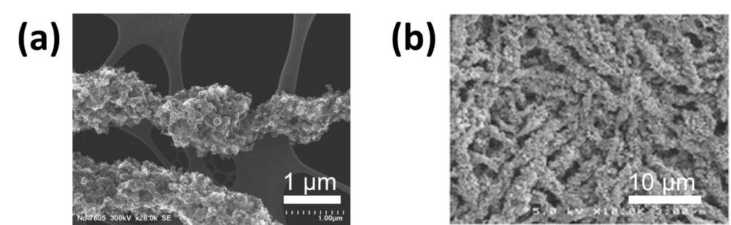
Figure 4. SEM micrographs of: (a) a single Pt/C/Nafion/PAA electrospun fiber (courtesy of Karren More at Oak Ridge National Laboratory) and (b) a top-down view of an electrospun nanofiber cathode mat. (Released)
Hydrogen/air fuel cell polarization data were collected with electrospun fiber mat electrode MEAs at 80oC, 100 percent relative humidity and ambient pressure (See Figure 5a), where the anode Pt loading was fixed at 0.1 mg/cm2 and the cathode Pt loading was either 0.107, 0.065 or 0.029 mg/cm2. [15] The performance of the 0.065 mgPt/ cm2 nanofiber cathode was superior to that of a decal cathode at a Pt loading of 0.104 mg/cm2. Also, there as only a modest drop in power output when the cathode loading was reduced from 0.107 to 0.065 mg/ cm2 (i.e., the maximum power density decreased only 15 percent, from 513 to 437 mW/cm2 when the Pt loading was reduced by about 40 percent).
The effect of binder on the initial performance and durability of nanofiber mat electrodes was also investigated. [16] Nanofiber cathodes were fabricated by electrospinning particle/polymer mixtures containing commercial Pt/C catalyst and a binder of either Nafion/PAA, Nafion/PVDF (with different Nafion/PVDF wt. ratios) or neat PVDF. Hydrogen/air fuel cell polarization curves for MEAs with cathodes containing 80/20 Nafion/PVDF and neat PVDF binders at a cathode Pt loading of 0.10 mg/cm2 are shown in Figure 5b. For comparison, data are also presented for a 0.10 g/cm2 nanofiber cathode with a binder of Nafion/PAA where the fiber composition is 64 wt.% Pt/C, 24 wt.% Nafion, and 12 wt.% PAA. Data were collected at 80°C with air and hydrogen at ambient pressure and 100 percent relative humidity.
![Figure 5. (a) Polarization curves for 5 cm2 MEAs with a Nafion 212 membrane and electrospun HiSpec™ 4000 cathodes and anodes. The Pt/C:Nafion:PAA weight ratio was fixed at 64:24:12. The anode Pt loading was 0.10 mg/cm2. The cathode Pt loading was: (Δ) 0.107 mg/cm2 (□), 0.065 mg/cm2, and (○) 0.029 mg/cm2. Performance of a decal MEA with cathode and anode Pt loadings of 0.104 mg/cm2 and 0.40 mg/ cm2, respectively is also shown (---); (b) Beginning-of-life polarization curves for 5 cm2 MEAs with a Nafion 211 membrane, a 0.10 mgPt/ cm2 electrospun cathode and a 0.10 mgPt/cm2 electrospun anode. The cathode binder (w/w) was: (●) Nafion/PAA (67/33), (▲) Nafion/PVDF (80/20), or (■) PVDF. Figure (a) Adapted with permission from [15] J. Electrochem. Soc., 160, F744 (2013), Copyright 2013, The Electrochemical Society. Figure (b) Reproduced with permission from [16] J. Electrochem. Soc., 163, F401 ( 2016). Copyright 2016, The Electrochemical Society.](https://hdiac.org/wp-content/uploads/2021/04/2017nano-electrospun-energy-conversion-storage_fig5-1024x392.jpg)
Figure 5. (a) Polarization curves for 5 cm2 MEAs with a Nafion 212 membrane and electrospun HiSpec™ 4000 cathodes and anodes. The Pt/C:Nafion:PAA weight ratio was fixed at 64:24:12. The anode Pt loading was 0.10 mg/cm2. The cathode Pt loading was: (Δ) 0.107 mg/cm2 (□), 0.065 mg/cm2, and (○) 0.029 mg/cm2. Performance of a decal MEA with cathode and anode Pt loadings of 0.104 mg/cm2 and 0.40 mg/ cm2, respectively is also shown (—); (b) Beginning-of-life polarization curves for 5 cm2 MEAs with a Nafion 211 membrane, a 0.10 mgPt/ cm2 electrospun cathode and a 0.10 mgPt/cm2 electrospun anode. The cathode binder (w/w) was: (●) Nafion/PAA (67/33), (▲) Nafion/PVDF (80/20), or (■) PVDF. Figure (a) Adapted with permission from [15] J. Electrochem. Soc., 160, F744 (2013), Copyright 2013, The Electrochemical Society. Figure (b) Reproduced with permission from [16] J. Electrochem. Soc., 163, F401 ( 2016). Copyright 2016, The Electrochemical Society.
The Nafion/PVDF and Nafion/PAA cathode MEAs generated similar polarization curves, with the Nafion/PVDF cathode MEA having slightly higher current densities at voltages less than 0.65 V and slightly smaller current densities at voltages greater than 0.65 V. The neat PVDF cathode MEA produced low power, but it worked better than expected (a maximum current density greater than 1 A/ cm2), considering the fact that there was no proton conducting ionomer in the cathode. It was also found that increasing the hydrophobicity of the cathode binder by replacing PAA with PVDF and decreasing the Nafion/ PVDF ratio slowed catalyst carbon support corrosion in the cathode, presumably by reducing the amount of water near the catalyst surface. [16]
Electrospun Li-ion Battery Electrodes
Lithium-ion batteries convert chemical energy into electrical energy through reversible redox reactions involving Li storage in the anode and cathode. A LIB is constructed from two or more cells connected in series and/or parallel, where each cell contains three components: an anode (typically graphite), a cathode (often LiMO2, where M = Co, Mn or Ni) and an ionically conductive
liquid electrolyte embedded in a porous polyolefin separator.
LIB electrodes are typically prepared by slurry casting a solution containing active material, conductive carbon (when needed) and polymer binder onto an electronically conductive current collector. While these slurry cast electrodes are used in all of today’s commercial batteries, such electrodes suffer from slow recharge rates due to Li+ transport limitations. The drawback of slurry
casting is its inability to provide internal porosity for electrolyte penetration in an easily controlled manner. New electrode manufacturing strategies would allow for the intelligent arrangement of LIB nanomaterials at the micron-scale, where particle/particle contacts and electrode porosity are optimized for high capacities and fast recharge rates.
Driven by successes with the electrospun fuel cell electrodes, Pintauro’s group has fabricated and tested a number of electrospun particle/binder anodes and cathodes for Li-ion batteries, including: (i) anodes containing titania nanoparticles, carbon powder and poly(acrylic acid); [17] (ii) anodes containing carbon powder and PVDF; [18] and (iii) cathodes containing LiCoO2
nanoparticles, carbon powder and PVDF (See Figure 6a). [19]
Nanofiber electrode performance in coin cells was exceptional, with higher capacities at fast charge/discharge rates, as compared to conventional electrodes. Figure 6b shows excellent rate capabilities for an electrospun LiCoO2-C/PVDF cell, where the gravimetric capacity at 2C (61 mAh g-1) is much greater than that of a slurry cast cathode of the same composition (0.25 mAh g-1). Similar results were obtained for capacities normalized with respect to electrode footprint and volume (i.e., areal and volumetric capacities) which are important for practical battery applications. The excellent performance of the electrospun electrodes is attributed to the unique fiber mat morphology which provides: (i) a large electrode/electrolyte interfacial area; (ii) good electrolyte
infiltration throughout the intra- and interfiber void space of the fiber mat; and (iii) short Li+ transport pathways between the electrolyte and active material in the radial fiber direction.
Ongoing work is focused on high capacity silicon anodes for next-generation Li-ion batteries. Si undergoes large volumetric changes during charging (e.g., a 300 vol.% change during the lithiation of Si); such extreme volume changes could be accommodated by the interfiber void space in a properly designed nanofiber mat anode. [20,21]
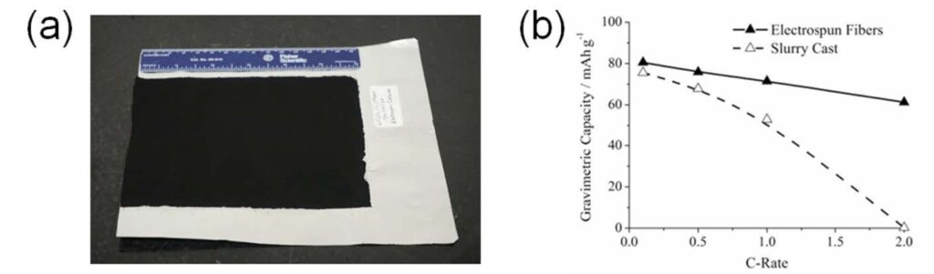
Figure 6. (a) As-electrospun nanofiber mat cathode composed of LiCoO2/C/PVDF and (b) Gravimetric capacity vs. C-rate for the nanofiber vs. slurry cast cathode in a half cell configuration. (Released)
Summary and Future Prospects
In this paper, representative examples and lab data are given to demonstrate the practicality and wide-ranging applicability of electrospinning for the fabrication of fuel cell and Li-ion battery components. The excellent performance of electrospun electrodes and membranes is a consequence of their unique multi-scale morphology and the ability to control this morphology via adjustment of electrospinning parameters and post-electrospinning processing steps. The nano-level structure is a consequence of the electrospinning process itself, where there is shear mixing at the spinneret tip augmented by the high extensional forces and rapid solvent evaporation of the fiber jet. Micron-level structure (e.g., the porosity, thickness, and distribution of reinforcing
fibers in a dense membrane or the fiber volume fraction in a Li-ion battery cathode) is controlled by nanofiber mat processing after electrospinning. The applications of electrospinning are practically unlimited and extend well beyond energy conversion and storage devices. For example, Pintauro’s group showed that an electrospun fiber mat of zirconium hydroxide nanoparticle in
a polyvinyl butyral binder was a highly effective sorptive/reactive media for the removal of toxic chemicals from air, [22] where such mats could be used in clothing and gas masks for military personnel. Clearly, more research and development is needed to fully exploit this transformative technology.
References
1. Reneker, D.H. and Chun, I. (1996). Nanometre diameter fibres of polymer, produced by electrospinning Nanotechnology, 7, 216- 223.
2. Choi, J., Lee, K.M., Wycisk, R., Pintauro, P.N., and Mather, P.T. (2008). Nanofiber network ion-exchange membranes. Macromolecules, 41(13), 4569-4572.
3. Ballengee, J.B. and Pintauro, P.N. (2011). Composite fuel cell membranes from dual- nanofiber electrospun mats. Macromolecules, 44(18), 7307-7314.
4. Sharaf, O.Z., and Orhann, M.F. (2014). An overview of fuel cell technology: Fundamentals and applications. Renewable and Sustainable Energy Reviews 32, 810-853.
5. Choi, J., Wycisk, R., Zhang, W., Pintauro, P.N., Lee, K.M., and Mather, P.T. (2010). High Conductivity Perfluorosulfonic Acid Nanofiber Composite Fuel-Cell Membranes. 3, 1245-1248.
6. Choi, J., Lee, K.M., Wycisk, R., Pintauro, P.N., Mather, P.T. (2010). Nanofiber composite membranes with low equivalent weight perfluorosulfonic acid polymers. J. Matter. Chem. 20(30), 6282-6290.
7. Park, J.W., Wycisk, R., Pintauro, P.N. (1015). Nafion/PVDF nanofiber composite membranes for regenerative hydrogen/ bromine fuel cells. J. Membrane Sci., 490, 103-112.
8. Park, J.W., Wycisk, R., Pintauro, P.N., Yarlagadda, V., and Nguyen, T.V. (2016) . Electrospun Nafion/Polyphenylsulfone Composite Membranes for Regenerative Hydrogen Bromine Fuel Cells. Materials, 9 (143), 2-15; doi:10.3390/ma9030143.
9. Park, J.W., Wycisk, R., Lin, G., Nguyen, T.V., and Pintauro, P.N., (2015). Electrospun Nafion/ PVDF Blended Nanofiber Membranes for Regenerative H2/Br2 Fuel Cells, 228 ECS Meeting, Phoenix (AZ) October 11-15. Abstract #1465.
10. Lin, G., Chong, P.Y., Yarlagadda, V., Nguyen, T.V., Wycisk, R.J., Pintauro, P.N., Bates, M., Mukerjee, S., Tucker, M.C., Weber, A.Z. (2016). Advanced Hydrogen-Bromine Flow Batteries with Improved Efficiency, Durability and Cost. J. Electrochem. Soc., 163(1) A5049-A5056.
11. Cho, K.T., Albertus, P., Battaglia, V., Kojic, A., Srinivasan, V., Weber, A.Z. (2013). Optimization and analysis of high-power hydrogen/bromine-flow batteries for gridscale energy storage. Energy Technol., 1, 596–608.
12. Cho, K.T., Ridgway, P., Weber, A.Z., Haussener, S., Battaglia, V., Srinivasan, V. (2012). High performance hydrogen/bromine redox flow battery for grid-scale energy storage. J. Electrochem. Soc., 159, A1806-A1815.
13. Kreutzer, H., Yarlagadda, V., Nguyen, T.V. (2012). Performance evaluation of a regenerative hydrogen-bromine fuel cell. J. Electrochem. Soc., 159, F331–F337.
14. Zhang, W. and Pintauro, P.N., (2011). High-Performance Nanofiber Fuel Cell Electrodes. ChemSusChem, 4, 1753-1757.
15. Brodt, M., Wycisk, R., and Pintauro, P.N. (2013). Nanofiber Electrodes with Low Platinum Loading for High Power Hydrogen/ Air PEM Fuel Cells. J. Electrochem. Soc., 160(8), F744-F749.
16. Brodt, M., Wycisk, R., Dale, N., and Pintauro, P.N. (2016). Power Output and Durability of Electrospun Fuel Cell Fiber Cathodes with PVDF and Nafion/PVDF Binders. J. Electrochem. Soc., 163(5), F401-F410.
17. Hayner, C.M., Zhao, X., and Kung, H.H. (2012). Materials for Rechargeable Lithium- Ion Batteries. Annu. Rev. Chem. Biomol. Eng. 2012.3, 445-471.
18. Self, E.C., Wycisk, R., Pintauro, P.N. (2015). Electrospun titania-based fibers for high areal capacity Li-ion battery anodes. J. Power Sources, 282, 187-193.
19. Self, E.C., McRen, E.C., Pintauro, P.N. (2016). High Performance Particle/Polymer Nanofiber Anodes for Li-ion Batteries using Electrospinning. ChemSusChem, 9(2), 208-215.
20. Self, E.C., McRen, E.C., Wycisk, R., Pintauro, P.N. (2016). LiCoO2-Based Fiber Cathodes for Electrospun Full Cell Li-ion Batteries. Electrochim. Acta, 214, 139-146.
21. Liu, L., Lyu, J., Li, T. Zhao, T. (2016). Well-constructed silicon-based materials as high-performance lithium-ion battery anodes. Nanoscale, 8, 701-722.
22. Wang, H.H., Yuan, S., Ma, D.L., Zhang, X.B., Yan, J.M. (2015) Electrospun materials for lithium and sodium rechargeable batteries: from structure evolution to electrochemical performance. Energy Environ. , 8(6), 1660.
23. Wycisk, R., Barpaga, D., LeVan, M.D., Pintauro, P.N. (2014) Electrospun zirconium hydroxide nanoparticle fabrics as sorptive/ reactive media. Adsorption, 20(2) 261-266.