


Summary
This article explores the effect of the print method and material on the impact resistance of a custom-fit, three-dimensional (3-D)-printed shoulder guard for use as protective gear by sports or tactical athletes, such as Warfighters or police/fire/first responders. A 3-D scan was performed on the right shoulder of a body opponent bag (BOB) dummy. This scan was used to generate a virtual shoulder guard model that was 3-D printed via fused deposition modeling (FDM) and stereolithography (SLA) using multiple brands and types of materials. Shoulder guards with and without incorporated through-holes were tested. A physical shoulder model was created out of Quikrete concrete and a ShockShield liner. The various shoulder guards were placed on the shoulder model, and a drop assembly was used to impact the guards. The impactor used was a weighted American football helmet, and the weight was set to match the momentum of a National Football League (NFL) tackle at impact. Motion capture and ground-embedded force plates were used to measure impact velocity and force and validate momentum at impact. The holed version of the Hatchbox polylactic acid (PLA) guard fractured at the fifth impact, and the solid version of the Raise3D guard fractured at the second impact. The guards that did not fracture were the SLA-printed Formlabs “Durable” and “Tough” solid guards, the Formlabs Durable holed guard, and the Hatchbox PLA solid guards, both with and without ethylene vinyl acetate (EVA) foam padding. Therefore, these are the suggested combinations of the print method and material for manufacture of custom-fit, 3-D-printed protective gear.
Introduction
Additive manufacturing (3-D printing) is a process that has become widely adopted in multiple fields over the past decade, with custom-fit protective gear for sports or tactical athletes being one of the most promising use cases. FDM is one of the most common methods of 3-D printing. It involves extruding a polymer filament through a heated nozzle to generate a print on a layer-by-layer basis. Materials commonly used for FDM printing are PLA and acrylonitrile butadiene styrene (ABS). Other materials used for FDM printing are less common but include polyethylene terephthalate glycol (PETG), nylon, polycarbonate, and some filaments with embedded carbon fiber. SLA is another frequently used print method that involves using a light source to cure liquid resin housed in a vat within the 3-D printer. Resin mixtures, which tend to be proprietary, are frequently referred to by their advertised names such as Durable or Tough by Formlabs.
The ability to combine 3-D scanning with 3-D printing provides an additional opportunity to manufacture devices with complex curvatures like those needed for the human body. Creating customized medical devices like casts and braces via 3-D printing is becoming more commonplace despite technical challenges associated with the practical logistics of manufacturing these devices. 3-D scanning has traditionally been constrained to expensive handheld scanners such as the Creaform Go!Scan20. However, advancements in scanning capabilities on smartphones like Apple’s Face ID technology on their iPhones have made scanning more accessible to large numbers of end users. Multiple pilot studies of the efficacy of custom-fit, 3-D-printed casts and braces have been published in recent years [1–5]. These studies consistently showed that the devices met or exceeded the performance of traditional casts and braces made from plaster or thermoplastics as related to injury healing and patient comfort and satisfaction.
Another potential application of 3-D-printed devices is in the form of protective body-worn gear. 3-D printing has been used for athletic applications such as shoe soles (although not necessarily custom), custom-fit helmet liners, and even soccer shin guards [6–8]. The prospect of custom-fit protection for sports and tactical athletes is intriguing, as it would provide a low-profile version of athletic equipment likely to increase speed and maneuverability. However, the feasibility of 3-D-printed devices in such an extreme environment is relatively unknown.
Several studies in the literature examined the impact resistance of 3-D-printed devices [9–13]. These studies evaluated the effects of parameters like layer thickness and infill pattern and density. However, they only tested small prints, such as dog bone-shaped samples, rather than full-scale wearable equipment. There have been no known studies to test the effects of the print method and material type on impact strength for a full-scale piece of wearable protective gear. Therefore, the objective of this study is to test the impact resistance of custom-fit, 3-D-printed shoulder guards made by multiple print methods and from multiple materials. The hypothesis is that each shoulder guard would break after the first impact but before the 10th impact.
Methods
The following methods describe the creation of the shoulder guards, the corresponding shoulder physical model, and the momentum requirements estimation. Additionally, the methods describe the drop guide assembly and method of impact force measurement as well as the drop process and subsequent impact velocity and momentum calculation as a means of verifying achieved momentum requirements.
Shoulder Guard Creation
The BOB dummy was chosen as the “test subject” for creating and testing custom-fit, 3-D-printed shoulder guards (Figure 1). A 3-D scan was performed on the right shoulder of the BOB by an in-house, iPhone-based, 3-D scanning app. The subsequent shoulder guard model (and print file) was also generated with in-house software. Two shoulder guard models were created, both 3 mm thick, with proprietary infill density—a solid version and a “holed” version meant to replicate commonly used lattice-type approaches to 3-D printing. There were two types of print methods used for the 3-D-print-tested shoulder guards: (1) FDM on a Raise3D Pro2 printer and (2) SLA on a Formlabs Form 2 printer. Two brands of filament were used with FDM printing—Raise3D PLA and Hatchbox PLA. There were two types of resin used with SLA printing—Formlabs Durable and Tough. The same shoulder guard model was used for each print, except for the holed versions, which involved the same original shoulder model file but with through-holes.
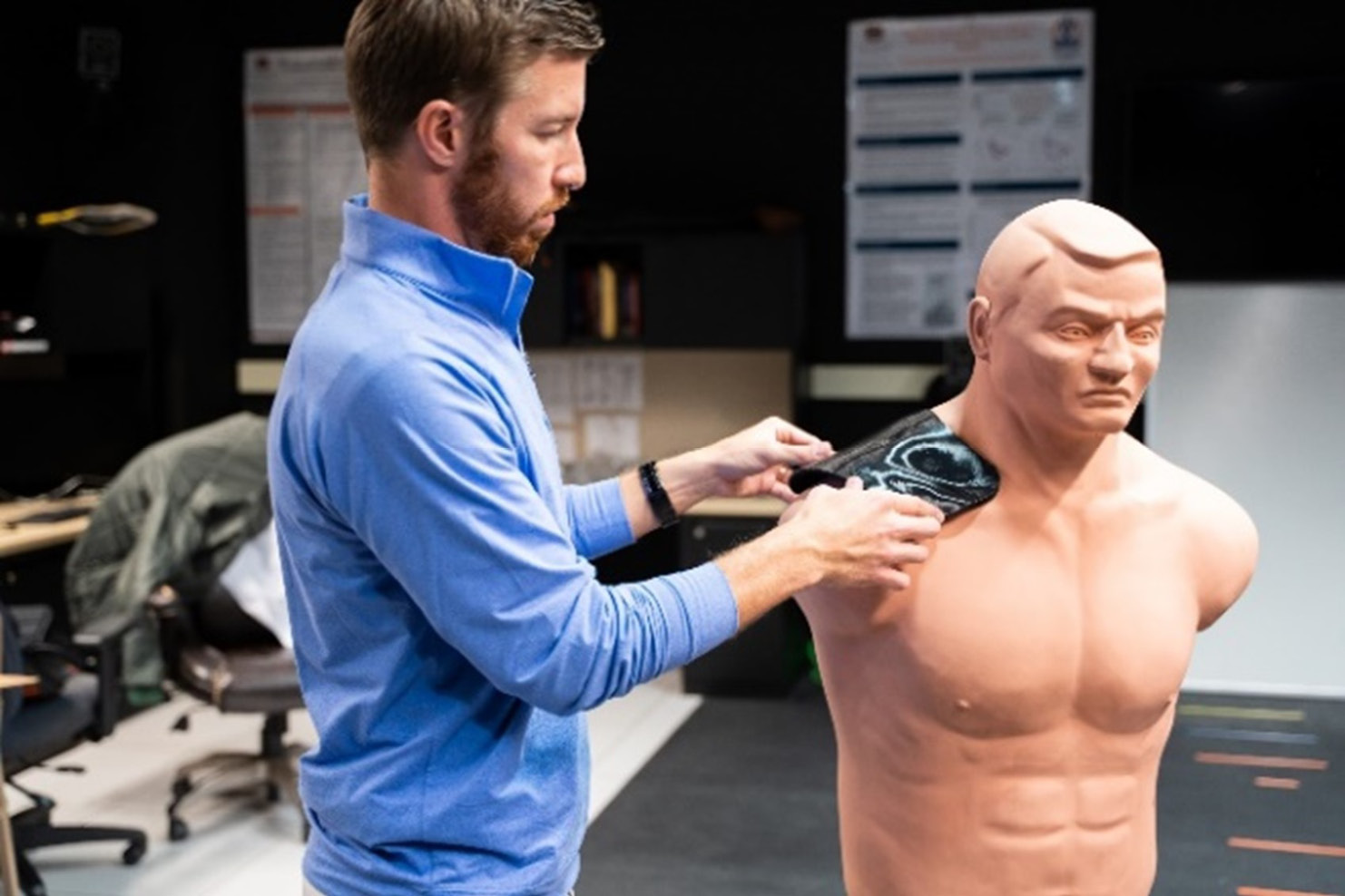
Figure 1. Custom-Fit, 3-D-Printed Shoulder Guards Fitting the BOB (Source: M. Zabala and J. Larson).
The first round of testing was performed on unpadded shoulder guards (Figure 2). A second round of testing was performed on Hatchbox PLA shoulder guards with and without 3-mm EVA foam padding. This included a special case that involved a 24-hour pause during the 3-D-printing process, which occurred approximately halfway through. This special case was meant to replicate an accidental stoppage midprint, such as the 3-D printer experiencing an unexpected and unmonitored power outage while printing a device with an extended print time.
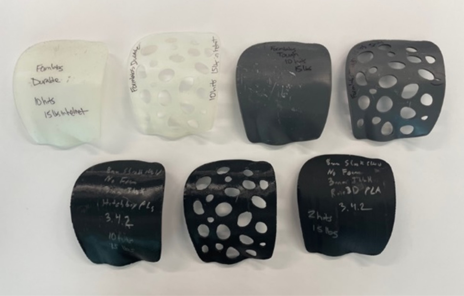
Figure 2. Shoulder Guards: (Top Row, Left to Right) Formlabs Durable Solid, Durable Holed, Tough Solid, and Tough Holed and (Bottom Row, Left to Right) Hatchbox PLA Solid, Hatchbox PLA Holed, and Raise3D PLA Solid (Source: M. Zabala and J. Larson).
Physical Shoulder Model Creation
It was determined that use of the BOB dummy for impact testing was not ideal, as the entire BOB setup would attenuate force prior to registration by ground-embedded force plates over which it would be placed during testing. Therefore, a representative physical model of only the BOB’s right shoulder was created. This was accomplished by using the shoulder scan to generate a virtual model file of a negative shoulder mold, which was 3-D printed and filled with Quikrete concrete and allowed to harden. The resulting concrete shoulder was then covered with an 8-mm-thick ShockShield liner (similar to ballistics gel) to represent soft tissue. The result of this process was a physical representation of the BOB’s right shoulder upon which the shoulder guards could be positioned for impact testing (Figure 3). In the figure, the setup was positioned on top of a concrete footer, which was set upon ground-embedded force plates.
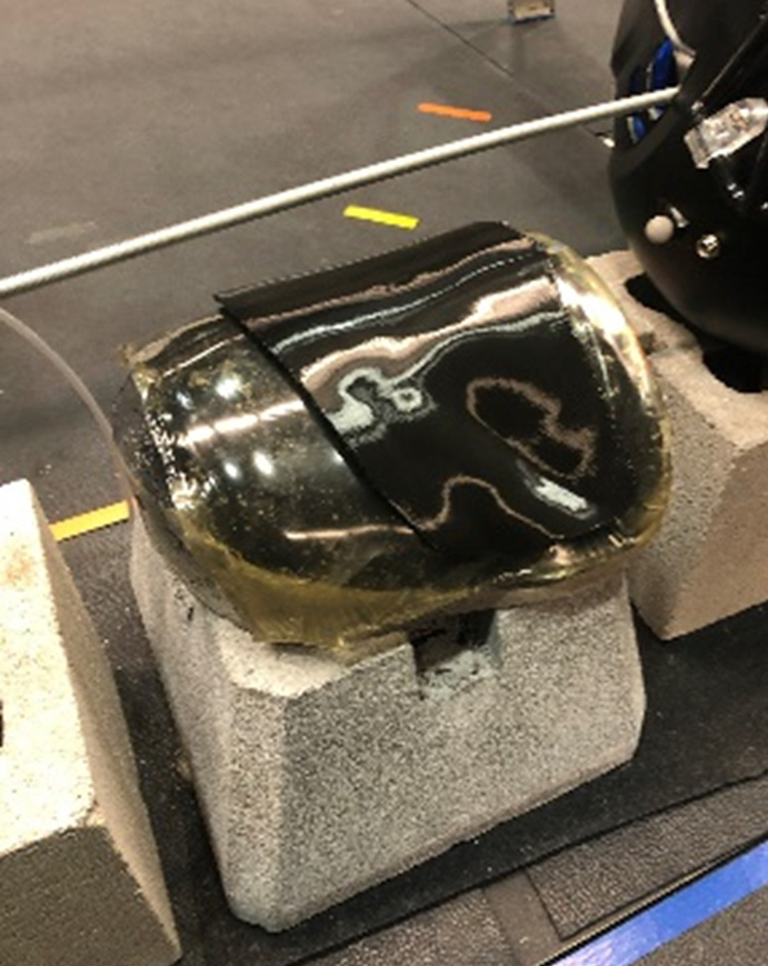
Figure 3. BOB Right Shoulder (Concrete With Overlaid ShockShield) With a Custom-Fit, 3-D-Printed Shoulder Guard (Source: M. Zabala and J. Larson).
Momentum Estimation
A weighted American football helmet was chosen as the impactor to represent an extreme scenario during athletic activity. Moreover, to produce an adequate representation of impact, an estimation was performed of the momentum of an NFL linebacker’s head during a maximum-speed tackle. A 95th percentile male head mass was considered: 5.377 kg (11.85 lbf) [14]. With an assumed tackle velocity of 20 mph, the resulting momentum of the head at impact during an NFL tackle was ~348 lbm-fps. (Note that this condition represented a legal tackle, with the head upright, and contact was made by the anterior surface of the helmet. This condition did not represent an illegal “targeting” tackle where the entire body was launched at the ball carrier and contact was made with the crown of the helmet.)
Preliminary tests in the Auburn University Biomechanical Engineering Lab provided an estimated impact speed of ~12 mph. Therefore, to match the momentum of an NFL tackle, the impactor (helmet and crossbar) weight needed to be ~19.8 lbf. The helmet used as the impactor for testing was a Schutt Vengeance Pro for adults.
Drop Guide and Impactor Assembly and Force Measurement
A cable-based guide assembly was built to generate an impact velocity of ~12 mph. Two cables were anchored in the ceiling of the 8-foot-tall lab space and at the floor to two 8-inch × 8-inch × 16-inch concrete blocks. The cables were routed through two eyelets at each end of a wooden dowel that was passed through the earholes of the football helmet (Figure 4). This figure shows a weighted American football helmet with a metal rod through the earholes. The rod has eyelets at the ends through which guide wires pass. Weights were added to the helmet such that the helmet, weights, and dowel assembly were ~19.8 lbf. The two concrete blocks and the concrete footer and shoulder assembly were all placed within the footprint of two AMTI ground-embedded force plates (AMTI BP400600, 2,000-lbf capacity) to measure peak impact force from the impacting helmet transferred through the guard, shoulder, and concrete footer. A rope was routed through a pulley mounted to the ceiling, and a release mechanism was attached to the end of the rope connected directly to the helmet/dowel impactor assembly.
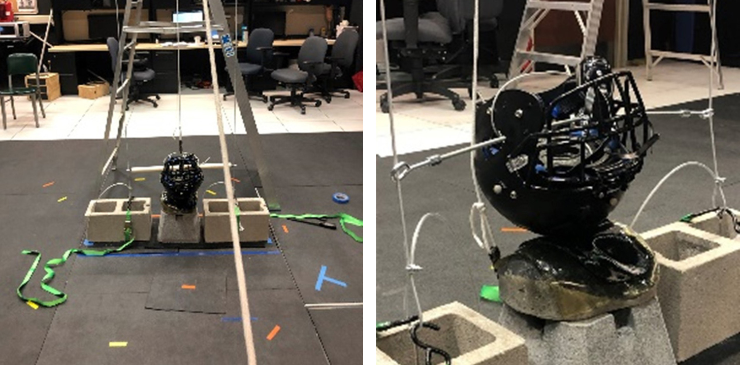
Figure 4. Setup for Impact Testing (Source: M. Zabala and J. Larson).
Drop Process
Each of the shoulder guards was tested until the 10th impact or until fracture. Prior to each drop, the force plates were zeroed to account for the weight of the two concrete blocks, the concrete footer, and the shoulder model (concrete and ShockShield). A research assistant raised the impactor assembly by pulling on the rope (routed through the pulley). A second research assistant located on a ladder near the top of the drop assembly then engaged the release mechanism to initiate the drop. Drops were performed 10 times or until the guard broke, whichever came first.
Impact Velocity and Momentum Calculation
A 10-camera Vicon motion capture system was used to track three retroreflectors placed with double-sided tape on the left, right, and center of the helmet. Impact was determined by detecting the first z-coordinate (height) minimum of the centroid of all three helmet markers. The slope of the centroid position for 15 frames prior to impact was calculated as the “impact velocity” for each test. Momentum was calculated as the product of impact velocity and impactor mass.
Results
This section details the achieved impactor momentum, along with other impact results such as impact force, impact velocity, and how many trials a guard withstood prior to breaking. The guard impact performance is provided in the two tables presented in this section.
Momentum
The momentum at impact for all the impact tests with an impactor weight of 19.8 lbf was a minimum of 314.9 lbm-fps and a maximum of 356.2 lbm-fps. The average momentum was 353.9 lbm-fps, which was only 1.7% greater than the target momentum of 348 lbm-fps.
Print Method and Material Type
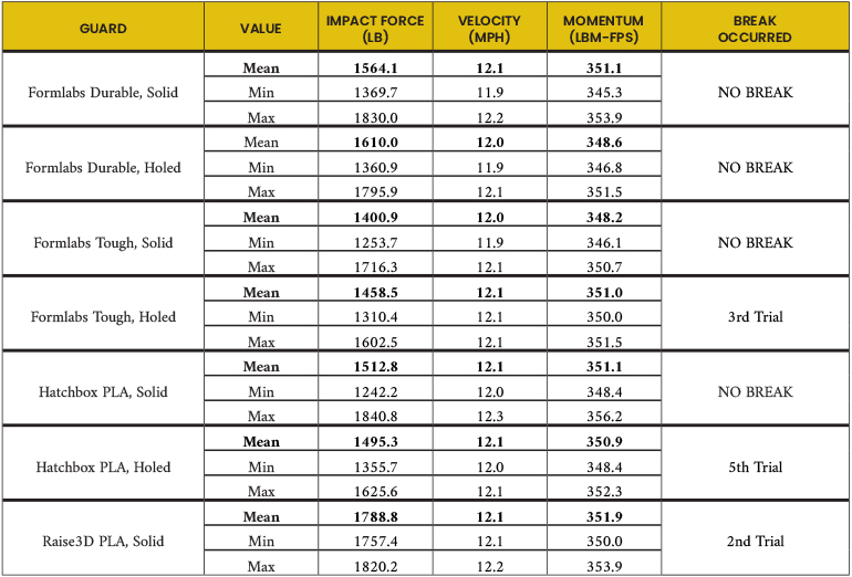
The shoulder guard prints that withstood impact for all 10 trials were the Formlabs Durable – Solid, Formlabs Durable – Holed, Formlabs Tough – Solid, and the Hatchbox PLA – Solid. The Formlabs Tough – Holed guard broke on the third trial. The Hatchbox PLA – Holed guard broke on the fifth trial. The Raise3D PLA – Solid guard was the only solid guard to break; it broke on the second trial. The results are listed in Table 1.
Table 1. Results of Testing the Effects of Varying Print Methods and Materials and the Presence of Through-Holes
With and Without Padding and Print Interruption
The shoulder guard prints that withstood impact for all 10 trials were the Hatchbox PLA with and without padding. The shoulder guard that was interrupted during the print process for 24 hours broke on the final 10th trial. A final reported test was added to the process to attempt to break the Hatchbox PLA padded shoulder guard. The impactor weight was increased from 19.8 lbf to 23.8 lbf. Additional impacts, beyond the initial 10 at 19.8 lbf, were conducted. The Hatchbox PLA foam padded guard broke on the 17th trial overall (on the seventh with additional mass – see Table 2 and Figure 5).
Table 2. Results of Testing of the Effects of Interrupted Printing and the Presence of Foam Padding
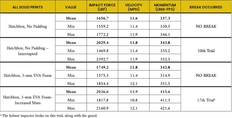
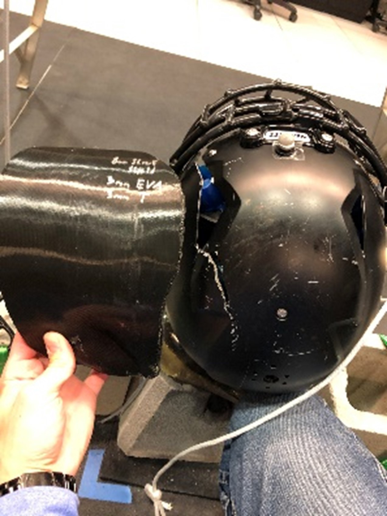
Figure 5. Final Impact of Helmet Weighted to 23.8 lbf Resulting in Fracture of Guard (Hatchbox PLA Solid) and Helmet (Source: M. Zabala and J. Larson).
Discussion
The hypothesis that the shoulder guards would break after the first but before the 10th impact trial was partially confirmed. All solid shoulder guards, except the interrupted print and the Raise3D brand PLA, withstood the 10 impacts. The holed version of the Formlabs Durable shoulder guard also withstood 10 impacts. However, the holed versions of the Formlabs Tough and Hatchbox PLA fractured during the third and fifth trials, respectively. This was not surprising, as including holes to the shoulder guard reduced the guard surface area and introduced stress concentrations at the locations of the holes. Also not surprising was that the interrupted print broke, albeit during the final 10th trial. This was because the 24-hour interruption likely resulted in a compromised abutment between the final layers prior to the pause and the initial layer upon print reinitiation. Had the interruption not occurred, the two layers would have been at higher temperatures, closer to the melting point of PLA, and formed a higher integrity bond. More surprising was that the solid version of the Raise3D PLA shoulder guard failed at the second impact trial. Although definitive conclusions cannot be drawn from this singular test, it does seem to suggest that brand influences impact strength of PLA, as no solid Hatchbox PLA shoulder guards broke except during the increased mass condition and at the 17th overall impact (Table 2, Figure 5). It is not clear why there seems to be a difference in performance across brands. However, it is reasonable to assume that various brands of filament manufacturers have unique subingredients and mixture combinations for a specific filament type like PLA that combine to produce different material property characteristics, including impact strength.
The performance of the devices impacted in this study provides evidence to support the feasibility of using custom-fit, 3-D-printed wearable protective guards by both sports and tactical athletes. The potential uses for sports athletes include shoulder guards, thigh pads, and knee pads for American football, hockey, and lacrosse players; shin guards for soccer players; and torso pads for motocross athletes. The potential uses for the tactical athlete are similar—low-profile body/torso protective gear, elbow pads, or knee pads. All these athletes would benefit greatly from protective gear made specifically to their bodies as opposed to discretely sized (small, medium, large, etc.) commercial off-the-shelf gear. It is likely that the custom-fit aspect of 3-D-printed gear would allow athletes to move more comfortably and freely and thus become more effective at their craft. Moreover, the Warfighters’ ability to increase speed and maneuverability would improve lethality and survivability.
The findings of this study also provide indirect evidence to support the use of custom-fit, 3-D-printed medical casts, splints, and braces (manufactured with the same methods) in settings like austere environments, as these devices would certainly experience mechanical loading conditions below what was tested. The results are subject to several limitations. First, only two brands of PLA and two types of resin were tested. Second, only a single design device was tested—a 3-mm-thick, custom-fit right shoulder guard for the BOB. Future tests should include multiple designs of multiple devices with various thicknesses. It is probable that parts of different sizes and contours will perform differently. Third, only 3-mm-thick EVA foam was used in the foam-lined conditions. Other types of foams with various thicknesses should also be used in future tests [15]. Fourth, the print orientation was consistent for each of the printed parts. It has been established in the literature that print orientation affects the strength of 3-D-printed parts [13, 16]. Also, infill density was not tested as an independent variable in this study. Future studies would benefit from an analysis of the effect of infill density on impact strength.
Another limitation is the minimal number of tests performed. Additional tests with large numbers of samples and impacts, likely into the hundreds, would provide a more thorough assessment of impact performance.
Finally, it is important to draw attention to the test’s design as it relates to what is likely experienced on the field of play due to an NFL tackle. The results of the testing described here included extremely high impact forces, ~1,500 lbf. During an actual tackle, the tackled ball player’s body will necessarily move with the tackler due to impact, absorbing the contact. However, the test setup in the lab resulted in an immobile shoulder model due to it being placed firmly on the ground and struck downward by the impactor. Therefore, the lab test more accurately represented an NFL tackle by driving the player into a concrete floor. This is obviously more extreme than what is typically experienced on the field of play but is potentially an improved representation of the degree of impact experienced by the tactical athlete.
Conclusions
This study evaluated the effect of print method (FDM vs. SLA) and material brand (Raise3D, Hatchbox) and type (PLA and Tough and Durable by Formlabs) on impact resistance to fracture. An additional variable was also tested—a 24-hour pause in the print process approximately halfway through the print. Impacts were designed to mimic an NFL tackle, although it was determined that the test setup was more extreme than likely experienced on the field of play. The results indicate that custom-fit, 3-D-printed protective gear can be appropriate for use in high-impact environments and for sports and tactical athletes, even based on the conservative testing conditions used in this study.
Acknowledgments
The authors would like to thank Grace Gray and Grant Hawkins for their contributions in collecting data in the lab as well as processing results.
References
- Fang, J.-J., C.-L. Lin, J.-.Y Tsai, and R.-M. Lin. “Clinical Assessment of Customized 3D-Printed Wrist Orthoses.” Applied Sciences, vol. 12, no. 22, 2022.
- Schlegl, A. T., R. Told, K. Kardos, A. Szoke, Z. Ujfalusi, and P. Maroti. “Evaluation and Comparison of Traditional Plaster and Fiberglass Casts With 3D-Printed PLA and PLA-CaCO(3) Composite Splints for Bone-Fracture Management.” Polymers (Basel), vol. 14, no. 17, 2022.
- Schwartz, D. A., and K. A. Schofield. “Utilization of 3D Printed Orthoses for Musculoskeletal Conditions of the Upper Extremity: A Systematic Review.” J. Hand Ther., vol. 36, no. 1, pp. 166–78, 2023.
- Van Lieshout, E. M. M., M. H. J. Verhofstad, L. M. Beens, J. J. J. Van Bekkum, F. Willemsen, H. M. J. Janzing, et al. “Personalized 3D-Printed Forearm Braces as an Alternative for a Traditional Plaster Cast or Splint; A Systematic Review.” Injury, vol. 53 Suppl. 3:S47–S52, 2022.
- Waldburger, L., R. Schaller, C. Furthmuller, L. Schrepfer, D. J. Schaefer, and A. Kaempfen. “3D-Printed Hand Splints Versus Thermoplastic Splints: A Randomized Controlled Pilot Feasibility Trial.” Int. J. Bioprint., vol. 8, no. 1, p. 474, 2022.
- Zastrow, M. “3D Printing Gets Bigger, Faster and Stronger.” Nature, vol. 578, pp. 20–24, 2020.
- Lee, H., R.-I. Eom, and Y. Lee. “Evaluation of the Mechanical Properties of Porous Thermoplastic Polyurethane Obtained by 3D Printing for Protective Gear.” Advances in Materials Science and Engineering, pp. 1–10, 2019.
- Alarifi, M. I., and I. M. Alarifi. “Comprehensive Structural Evaluation of Composite Materials in 3D-Printed Shin Guards.” Journal of Materials Research and Technology, vol. 27, pp. 6912–6923, 2023.
- Othman, F., H. B. Ali, and T. F. Alani. “Influence of Layer Thickness on Impact Property of 3D-Printed PLA.” International Research Journal of Engineering and Technology, vol. 5, no. 2, pp. 1–4, 2018.
- Mishra, P. K., P. Senthil, S. Adarsh, and M. S. Anoop. “An Investigation to Study the Combined Effect of Different Infill Pattern and Infill Density on the Impact Strength of 3D Printed Polylactic Acid Parts.” Composites Communications, vol. 24, 2021.
- Rajpurohit, S. R., and H. K. Dave. “Impact Strength of 3D Printed PLA Using Open Source FFF-Based 3D Printer.” Progress in Additive Manufacturing, vol. 6, no. 1, pp. 119–131, 2020.
- Tanveer, M. Q., A. Haleem, and M. Suhaib. “Effect of Variable Infill Density on Mechanical Behaviour of 3-D Printed PLA Specimen: An Experimental Investigation.” SN Applied Sciences, vol. 1, no. 12, 2019.
- Tezel, T., M. Ozenc, and V. Kovan. “Impact Properties of 3D-Printed Engineering Polymers.” Materials Today Communications, vol. 26, 2021.
- Yoganandan, N., F. A. Pintar, J. Zhang, and J. L. Baisden. “Physical Properties of the Human Head: Mass, Center of Gravity and Moment of Inertia.” J. Biomech., vol. 42, no. 9, pp. 1177–92, 2009.
- Kao, Y.-T., A. R. Amin, N. Payne, J. Wang, and B. L. Tai. “Low-Velocity Impact Response of 3D-Printed Lattice Structure With Foam Reinforcement.” Composite Structures, vol. 192, pp. 93–100, 2018.
- Saini, J. S., L. Dowling, J. Kennedy, and D. Trimble. “Investigations of the Mechanical Properties on Different Print Orientations in SLA 3D Printed Resin.” Proceedings of the Institution of Mechanical Engineers, Part C: Journal of Mechanical Engineering Science, vol. 234, no. 11, pp. 2279–2293, 2020.
Biographies
Michael E. Zabala is the director of the Auburn University Biomechanical Engineering Lab, where he focuses on the biomechanics of human performance and injury prevention. He has a long history of research involving 3-D scanning and printing of custom devices for the human body and a strong collaboration history with the Auburn University Football Program. Some of his other research endeavors have included anterior cruciate ligament (ACL) injury prevention and lower-limb prostheses and exoskeleton design and control. Dr. Zabala holds a bachelor’s degree in mechanical engineering from Auburn University and a master’s degree and Ph.D. in mechanical engineering from Stanford.
Jacob S. Larson is the director of engineering at XO Armor, where he focuses on developing cutting-edge 3-D scanning and manufacturing capabilities. He has successfully led research teams at XO Armor for 7+ years as a graduate student and the engineering director. His projects range from injury prevention in athletes using nonlinear dynamics analysis to creating custom 3-D-printed medical devices for Veterans Administration hospitals. Dr. Larson holds a bachelor’s degree in mechanical engineering from Valparaiso University and a Ph.D. in mechanical engineering from Auburn University.